Tag Archives: Arduino
DAT302 – Demonstrating the system
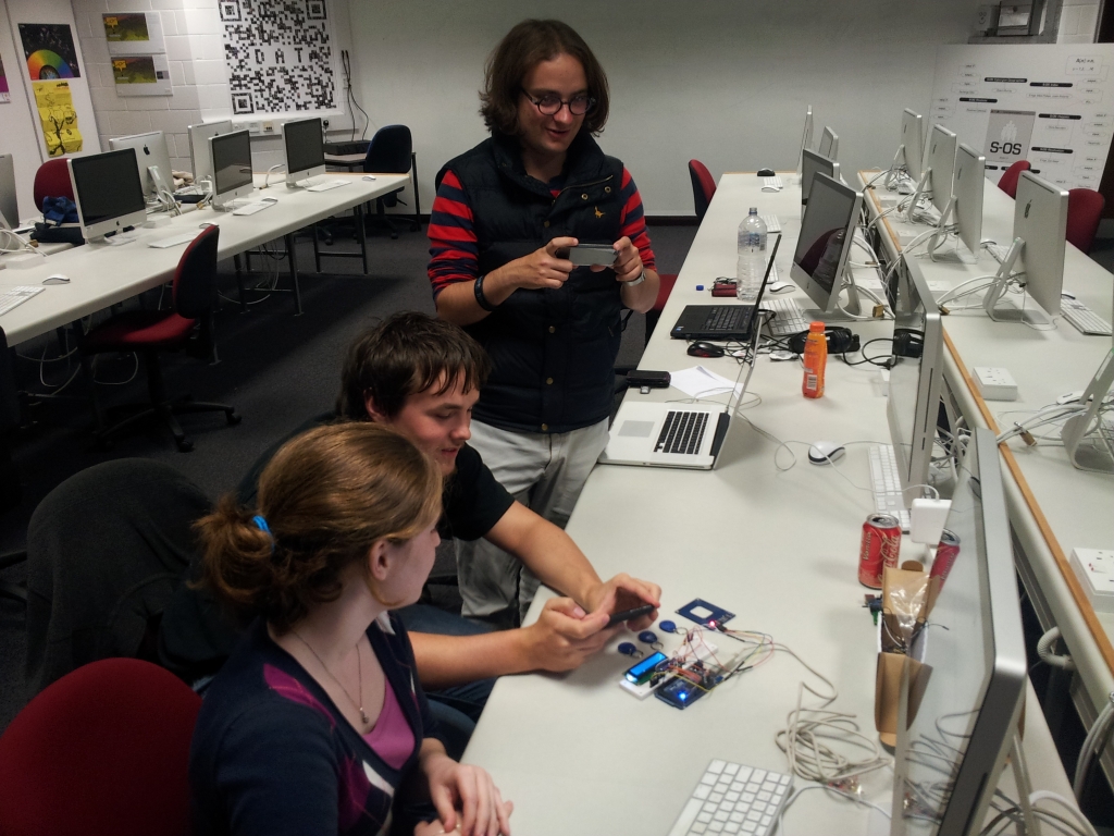
DAT302 – RFID
The RFID reader uses a serial connection with the Arduino to pass data to it. The easiest way to do this is to use the pins that are also used for the USB serial connection; the disadvantage of this is that the USB connection cannot be used and that there is only one. The SoftwareSerial library allows us to create serial connections with other pins.
We had a problem with our code for the RFID reader where it would freeze the Arduino unless it was able to read an RFID tag. It turned out that we were using an old version of Arduino and since Arduino 1.0 SoftwareSerial has been based on NewSoftwareSerial which fixed the freezing problem. Another problem we had was that we were using pins on the Arduino Mega 2560 that do not support a feature necessary for SoftwareSerial. Both of these problems would have been solved by actually reading the reference.
We made use of the LCD display used in Fickleduino to display the RFID tags owners’ names.
DAT301 – Fickleduino Conceptual
Our concept was that of a complaining device that could never be happy; that through a simple text display could provoke humans into vain attempts to please it and eventually become annoyed by it.
Everything the Fickleduino is aware of, it will complain about. If a user is too close they are invading it’s personal space, if they are too far it complains of loneliness. There is no happy middle ground, if the value is above or below or equal to a set point it will complain.
It would be possible for many senses could be added (Hot – Cold, Light – Dark, Wet – Dry, Fast – Slow, Near- Far, Loud – Quiet).
The purpose of Fickleduino is to see how people interact with inanimate objects that display awareness and personality via text.
DAT301 – Fickleduino Technical
For Fickleduino we had to stretch our technical ability with the arduino. It was the first time any of us had used a LED display or ultrasonic rangefinder with one. I bought the display as part of a kit along with a number of sensors including the rangefinder, light dependent resistors(LDRs) and various other parts.
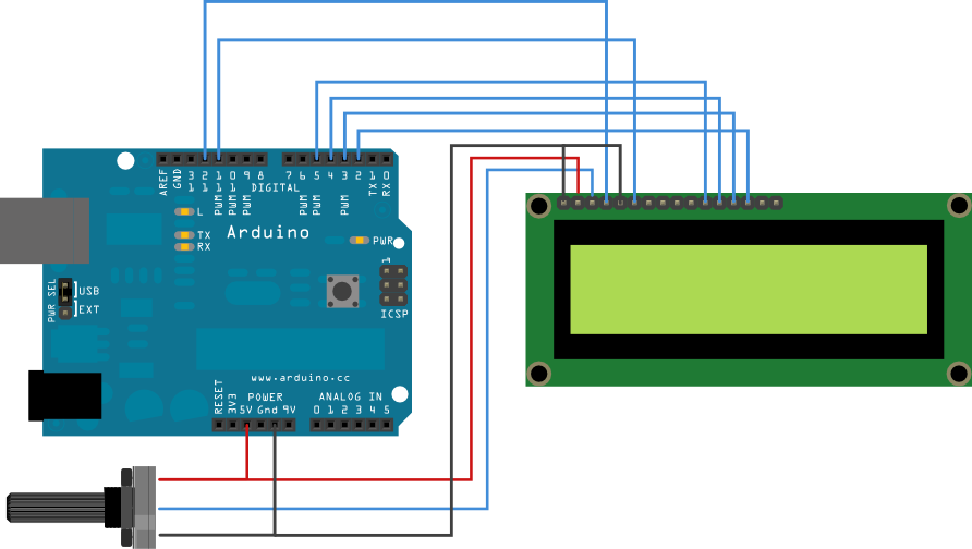
We found a simple wiring diagram for wiring the LCD in 4bit mode, in this mode it can only display ASCII characters but this was fine for our purposes. Wiring in 8bit mode would involve additional wires.
The diagram doesn’t show it but you also have to provide power to A – pin15 (positive) and K – pin16 (negative) on the display for the back light.
The Arduino website has these resources:
http://www.arduino.cc/en/Tutorial/LCDLibrary
http://arduino.cc/en/Reference/LiquidCrystal
In a simple Arduino program you may want something to happen at a regular interval like toggling a LED:
void loop() {
  digitalWrite(13, HIGH);
  delay(1000); // wait for a second
  digitalWrite(13, LOW);
  delay(1000); // wait for a second
}
As a single threaded device the Arduino completely freezes during these delays so if you wanted to have multiple things run at different intervals for example every 300ms and every 500ms, using delay is not practical.
unsigned long updateLastMillis = 0;
unsigned long scrollLastMillis = 0;

boolean cycleCheck(unsigned long *lastMillis, unsigned int cycle)
{
  unsigned long currentMillis = millis();
  if(currentMillis - *lastMillis >= cycle){
    *lastMillis = currentMillis;
    return true;
  }else{
    return false;
  }
}
void loop(){
  if(cycleCheck(&scrollLastMillis, 300)){
    // Do stuff
  }
  if(cycleCheck(&updateLastMillis, 500)){
    // Do stuff
  }
}
The cycleCheck function was written by dmesser and posted on the Arduino forum. This useful function allows you to create multiple timers and avoid using delay.
Combining the two of these together allowed us to marquee the text on the 16×2 LCD display with independent timings from the sensors collecting information.
Every 300ms the Arduino incremented a counter which served as the offset for a 16 character long substring of the output message. The output message contained three dash separated copies of the actual message to be displayed so that when it reached the end of the message it would loop back around continuously.
Each sensor has it’s own class that encapsulated code specific to it and made it modular; each have a getValue() and complain() method which sets the currently displayed message to one of it’s pre-written complains based on whether it’s higher or lower than the middle value. The Light class made use of an adaptive middle value as different lighting environments give very different values despite appearing to be the same with human eyes.

