![]()
Full readme: here.
Research was carried out to identify the necessary components for the project and the means of operating them alongside development. Specialist parts were purchased and ordered along with a number of spares so that in the eventuality of components failing they could serve as immediate replacements. Development of the main components was done in isolation from each other to ensure modularity for potential future expansion and clarity in the code.
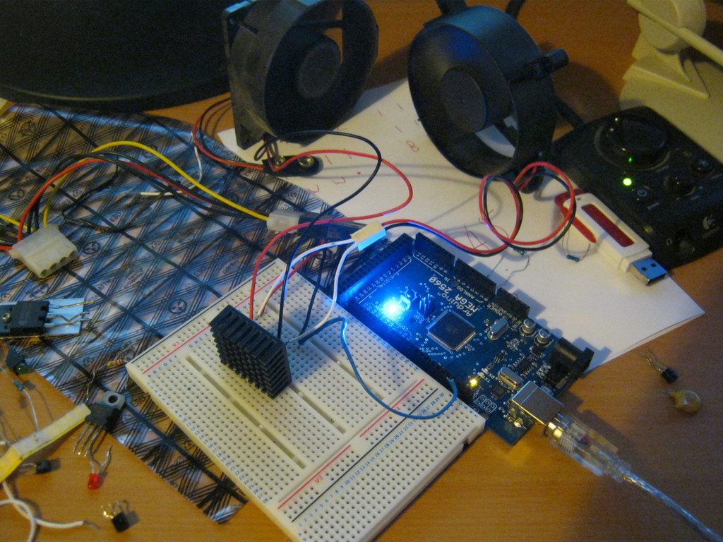
Work on the device itself started by creating a code function for calculating the speed at which each of the fans will need to run at to provide full three hundred and sixty degree control over wind direction. I chose to use processing for this task as I could create a visual interface and use it to send information to an arduino using a serial connection. I chose to use them for their simplicity and open source design ethic which fosters creativity and hobbyist development.
The software calculates the positions of each fan in a circle and measures the distance from the nearest position/s to the required angle. This distance is then mapped and converted into a percentage figure for the speed of each fan. This is mapped again to a value between zero and 255 which is accepted for arduino’s analogOut function for controlling its Pulse Width Modulation duty cycle. If the duty cycle – which is the percentage of the time that something is on – on a 12v signal is 50% then the effective voltage is 6v as the signal switches on and off very rapidly. Through this I can programmatically control the speed at which the fans run. As the arduino only outputs a maximum of 5v and I required 12v I experimented with MOSFET transistors. When powered by the 5v signal from the arduino the transistor allows current on a 12v rail from a computer power supply to pass through. As this is switching rapidly for the PWM signal it has the effect of amplifying it.

For the sake of simplicity I replaced the transistor with a ULN2003 DIP chip which could do the job for all of the fans in a single component.

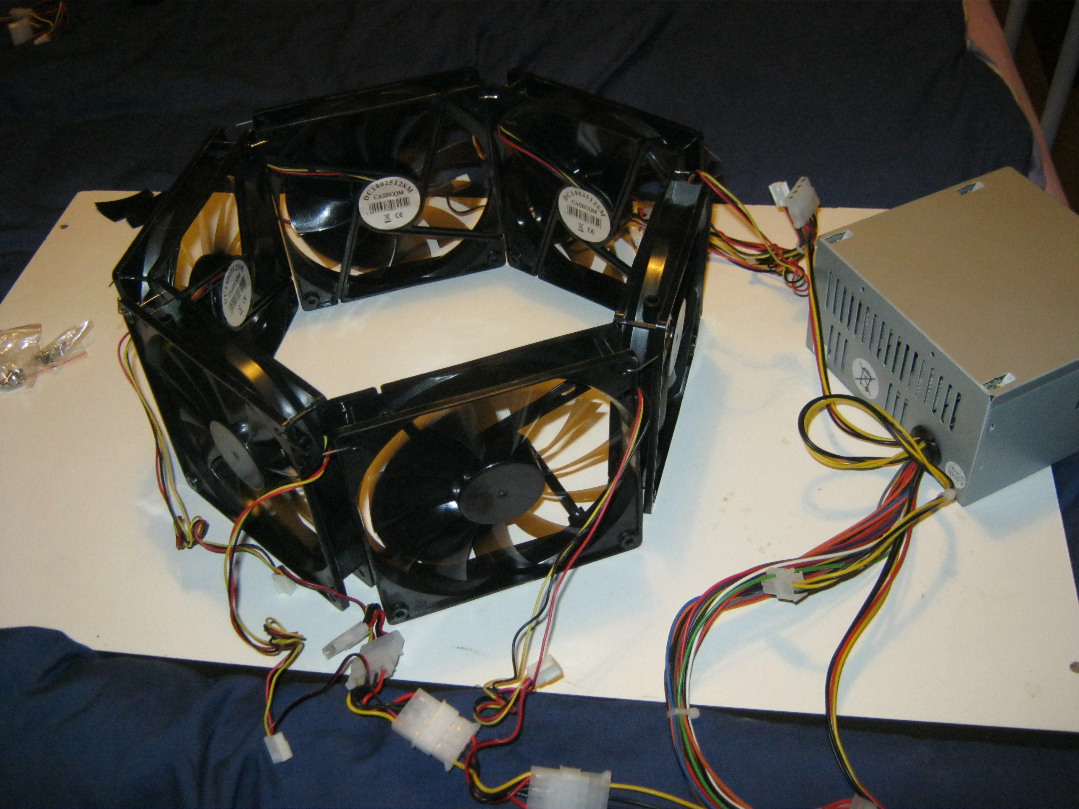
The wind portion of the device has six 140mm 12 volt desktop computer fans arranged in a ring facing inwards so that they draw air from the surrounding area.

After assembling this I improved the software by adding controls so that users can manually manipulate the device.

The second major component was the temperature sensor that would be necessary for controlling the heating system which would need to know the current temperature so that it could switch off when above the target temperature of on when below it. For this I used a digital thermometer chip which can be run off the arduino. The software on the arduino board reads this information and uses it to calculate the difference between the desired temperature and the current one. From this the states of heating and cooling elements can be controlled. This feedback loop regulates the system continuously.

The final component was the method for heating the space. After considering the use of heating elements I decided to use light bulbs as the source of heat. Wishing to avoid meddling with mains electricity I chose to use a remote control plug kit. I took apart the remote and worked out how it functioned so that I could circuit bend it for control by the arduino. Eventually I got the system working but during testing it inexplicably stopped functioning.

I decided to go for a more elegant yet more dangerous solution and use simple relays instead which I wired into the base of the three desk lamps for safety. Out of each lamp are two lines, when 12 volts are passed through it the relays switch on providing power to the 60 watt bulb. The three lamps were positioned around the fans pointing inwards. The lamps heat up the air within the space. A limitation of this open system is that new colder air is blown into the device and the warm air exits it through a combination of convection currents and the effect of the fans. In later versions this would be addressed with an enclosure that helps conserve air within the system whilst allowing venting to assure a quick transition between temperatures and user access.

At the end of development the separate elements were brought together and a single piece of arduino code was created to control them containing an even more simplified version of the simple analogue firmata. A reserved analogue pin was used to receive the target temperature from the processing sketch which it compares against the current temperature and controls the lamps. Due to the calculations involved I left fan control handling to the processing sketch, later versions may have greater independence from the host computer.
Final wiring diagram:


Latest Arduino Source:
#include <Firmata.h> #include <OneWire.h> OneWire ds(2); byte data[12]; byte analogPin = 0; int lamps[3]; float tTemp = 20; void analogWriteCallback(byte pin, int value){ if(pin == 3) { tTemp = (value-128)/2; return; } if (IS_PIN_PWM(pin)) { pinMode(PIN_TO_DIGITAL(pin), OUTPUT); analogWrite(PIN_TO_PWM(pin), value); } } void setup(){ Firmata.setFirmwareVersion(0, 1); Firmata.attach(ANALOG_MESSAGE, analogWriteCallback); Firmata.begin(57600); pinMode(13,OUTPUT); pinMode(28,OUTPUT); pinMode(26,OUTPUT); pinMode(24,OUTPUT); } void loop(){ controlLamps(getTemp(),tTemp); //Serial.println(getTemp()); while(Firmata.available()) { Firmata.processInput(); } } void controlLamps(float currentTemp, float targetTemp){ float delta = currentTemp - targetTemp; //delta = -2; if(delta <= 1){ digitalWrite(28,HIGH); digitalWrite(26,LOW); digitalWrite(24,LOW); } if(delta <= -2){ digitalWrite(28,HIGH); digitalWrite(26,HIGH); digitalWrite(24,LOW); } if(delta <= -4){ digitalWrite(28,HIGH); digitalWrite(26,HIGH); digitalWrite(24,HIGH); } delay(200); } float getTemp(){ byte i; byte present = 0; byte addr[8]; if (!ds.search(addr)){ ds.reset_search(); } ds.reset(); ds.select(addr); ds.write(0x44,1); delay(1000); present = ds.reset(); ds.select(addr); ds.write(0xBE); for ( i = 0; i < 9; i++) { data[i] = ds.read(); } int tempdata = data[0]*1; return float(tempdata/2)+(float((tempdata%2)*5)/10); }Latest processing source:
import processing.serial.*; import cc.arduino.*; import controlP5.*; ControlP5 control; float windSpeed = 50; float angleKnob = 0; Arduino arduino; XMLElement xml; float angle = 0; float temp = 25; int additional = 0; fans f; void setup(){ frameRate(15); smooth(); size(200,200); f = new fans(6, 33, 100); arduino = new Arduino(this, Arduino.list()[0], 57600); arduino.pinMode(3, Arduino.INPUT); arduino.pinMode(7, Arduino.OUTPUT); arduino.pinMode(8, Arduino.OUTPUT); arduino.pinMode(9, Arduino.OUTPUT); arduino.pinMode(10, Arduino.OUTPUT); arduino.pinMode(11, Arduino.OUTPUT); arduino.pinMode(12, Arduino.OUTPUT); control = new ControlP5(this); control.addSlider("windSpeed",0,100,50,5,5,100,10); control.addKnob("angleKnob",0,360,0,5,160,40); } void draw(){ getData(); f.update(); f.display(); // println(round(f.getFans()[1])); arduino.analogWrite(3, round(temp*2)+128); f.setStrength(windSpeed); angle = angleKnob; arduino.analogWrite(12, round(map(f.getFans()[0], 0,100,0,255 )) + additional); arduino.analogWrite(11, round(map(f.getFans()[1], 0,100,0,255 )) + additional); arduino.analogWrite(10, round(map(f.getFans()[2], 0,100,0,255 )) + additional); arduino.analogWrite(9, round(map(f.getFans()[3], 0,100,0,255 )) + additional); arduino.analogWrite(8, round(map(f.getFans()[4], 0,100,0,255 )) + additional); arduino.analogWrite(7, round(map(f.getFans()[5], 0,100,0,255 )) + additional); } void getData(){ //angle = constrain(angle + random(-5,5),0,360); /* String url = "http://www.isleofwightweather.com/rss.xml"; xml = new XMLElement(this, url); String desc = xml.getChildren("channel/item/description")[0].getContent(); String[] strs = split(desc,'|'); float angle = float(match(strs[10], "[0-9,.]+")[0] ); temp = float(match(strs[2], "[0-9,.]+")[0] ); */ f.setAngle(angle); }class fans{ float angle; float strength; int numFans; float segAng; float[] fans = new float[12]; float[] posX = new float[12]; float[] posY = new float[12]; float angPosX; float angPosY; fans(int newNumFans, float newAngle, float newStrength){ strength = newStrength; angle = newAngle; numFans = newNumFans; segAng = 360/numFans; for(int i = 0; i < numFans;i++){ float X = (cos(radians(i*segAng)) * (80 - i)) + 100; float Y = (sin(radians(i*segAng)) * (80 - i)) + 100; posX[i] = X; posY[i] = Y; } } void display(){ background(50,150,200); //angle++; if(angle > 360) angle = 0; pushStyle(); stroke(255,0,0); strokeWeight(5); line(width/2, height/2, getAngPosX(angle,strength/2),getAngPosY(angle,strength/2)); popStyle(); for(int i = 0; i < numFans;i++){ float X = (cos(radians(i*segAng)) * (80 - i)) + width/2; float Y = (sin(radians(i*segAng)) * (80 - i)) + height/2; pushStyle(); fill(map(fans[i],0,100,0,255)); ellipse(X, Y, 25, 25); popStyle(); } } void update(){ for(int i = 0; i < numFans;i++){ fans[i] = 0; if(angle >= ((i-1)*segAng)&&(angle < ((i+1)*segAng))){ fans[i] = map(dist(getAngPosX(angle,80),getAngPosY(angle,80),posX[i],posY[i]),80,0,0,strength); if((i == numFans-1)&&(fans[i-1] == 0)){ fans[0] = 100 - fans[i]; } } } } float[] getFans(){ return fans; } void setStrength(float newStrength){ strength = newStrength; } void setAngle(float newAngle){ angle = newAngle; } private float getAngPosX(float a, float r){ return (cos(radians(a)) * r) + width/2; } private float getAngPosY(float a, float r){ return (sin(radians(a)) * r) + height/2; } }