Author Archives: Jo Redwood

About Jo Redwood

Student at the University of Plymouth, studying digital art and technology.

DAT301 – Bioresponsive Game

We were demonstrated and introduced to a number of biometric recording devices including a brain wave measuring headset called a MindWave and a biofeedback sensor kit which had  several different sensors. Based on this we had to create an interactive project making use of this technology.

Writing this after the presentation, it’s fair to say that none of the group were happy with the outcome. We felt that the main problem was the lack of a solid and interesting concept and appealing aesthetics that related to it.

We decided for the sake of variety to avoid Arduino and were attracted to the idea of producing a game that was affected by the level of stress experienced by the player. To get an early start I proposed porting over a game I made in flash in the first year (the poorly named Klepto1), into Processing as a base to build of off. I was more concerned with the technical detail of the programming with extensive use of object orientated programming and making it flexible for the group to use. After this we left completing the remainder of the project too late and had to rush, dropping the use of live data and then there was also confusion over what pre-recorded data we were using. We believe we can avoid this happening again.

DAT302 – Technical

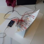
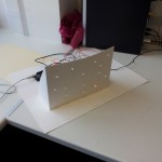
The prototype uses of 3 sets of 5 LEDs, each LED is soldered to two 30cm long wires which are soldered into a positive and negative header for the sets. This means that the LED sets can be easily plugged into a bread board or directly into an Arduino. The soldering was fairly time consuming but it allowed for quick assembly.

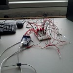
We realised that the Arduino would not be able to provide enough power for the LEDs on it’s own so we decided to make use of the ULN2003 chips I used in Weather Transplant, the 470 Ohm resistors supplied with the LEDs  and an adjustable transformer to get the correct voltage.

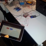
To control the wall we needed to create a touch interface, the easiest way to do this and to make it multi-platform was to create a web application. The web application updated a MySQL database via PHP and displayed the data on a different page. This page is then read by a processing sketch (VoteBridge) that sends the data via the serial port to the Arduino.

And as usual, here is the code:

Processing

import processing.serial.*;

Serial myPort;
String votes;
Timer timer = new Timer(500);

void setup()
{
  size(200, 200);
  String portName = Serial.list()[0];
  myPort = new Serial(this, portName, 9600);
}

void fetchData(){
  String[] data = loadStrings("http://pluxel.co.uk/thevision/feed.php");
  votes = data[0];
}

void draw() {
  timer.update();
  if(timer.active()){
    fetchData();
    myPort.write(votes);
    println("Sent: "+votes);
  }

}

Arduino

int redPins[] = {22, 24, 26, 28, 30};
int bluePins[] = {32, 34, 36, 38, 40};
int whitePins[] = {42, 44, 46, 48, 50};

int redVotes = 0;
int blueVotes = 0;
int whiteVotes = 0;

unsigned long scrollLastMillis = 0;

boolean cycleCheck(unsigned long *lastMillis, unsigned int cycle)
{
  unsigned long currentMillis = millis();
  if(currentMillis - *lastMillis >= cycle){
    *lastMillis = currentMillis;
    return true;
  }else{
    return false;
  }
}

String txtMsg = "";
char s;

void setup() {
  Serial.begin(9600);
  Serial.flush();
  // initialize the digital pin as an output.
  pinModes(redPins);
  pinModes(bluePins);
  pinModes(whitePins);
}

void pinModes(int pins[]){
  for(int i = 0; i < 5; i++){
    pinMode(pins[i], OUTPUT);
  }
}

void reset(int pins[]){
  for(int i = 0; i < 5; i++){
    digitalWrite(pins[i], LOW);
  }
}

void loop() {
  if(cycleCheck(&scrollLastMillis, 1000)){
       while (Serial.available() > 0) {
        s=(char)Serial.read();
        if(s == 'n' || s == 'r') {
            txtMsg = "";
        }else{
            txtMsg +=s;
        }
    }
    if(txtMsg != "") updateVotes(txtMsg);
    txtMsg = "";
  }

  if(redVotes > 5 || blueVotes > 5 || whiteVotes > 5 ){
    boolean victory = false;
    // Voting has finished
    if(redVotes > 5){
      cycle(redPins, 100);
      victory = true;
    }
    if(blueVotes > 5){
      cycle(bluePins, 100);
      victory = true;
    }
    if(whiteVotes > 5){
      cycle(whitePins, 100);
      victory = true;
    }
  }else{
    displayVotes(redPins, redVotes);
    displayVotes(bluePins, blueVotes);
    displayVotes(whitePins, whiteVotes);
  }
}

void updateVotes(String txt){
  Serial.println("Reading: "+txt);
  redVotes = txt.substring(0,3).toInt();
  blueVotes = txt.substring(4,7).toInt();
  whiteVotes = txt.substring(8,11).toInt();
  reset(redPins);
  reset(bluePins);
  reset(whitePins);
}

void displayVotes(int pins[], int votes){
  for(int i = 0; i < votes; i++){
    digitalWrite(pins[i], HIGH);
  }
}

void cycle(int pins[], int period) {
  digitalWrite(pins[0], HIGH);
  delay(period);
  digitalWrite(pins[0], LOW);
  digitalWrite(pins[1], HIGH);
  delay(period);
  digitalWrite(pins[1], LOW);
  digitalWrite(pins[2], HIGH);
  delay(period);
  digitalWrite(pins[2], LOW);
  digitalWrite(pins[3], HIGH);
  delay(period);
  digitalWrite(pins[3], LOW);
  digitalWrite(pins[4], HIGH);
  delay(period);
  digitalWrite(pins[4], LOW);
}
DAT302 – St. Blazey

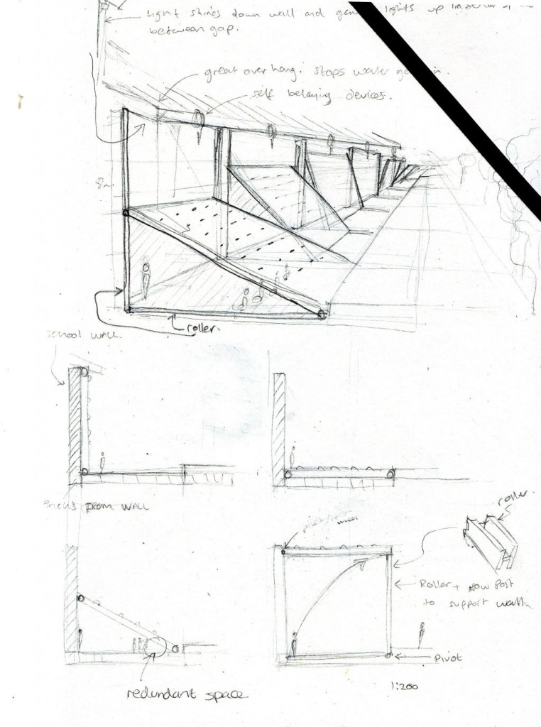
Our second project collaborating with the architects focused on the small Cornish town of St Blazey near St Austell and the Eden Project. Once a hub for mining, historically copper and tin but later china clay, this industry has mostly disappeared from the town.

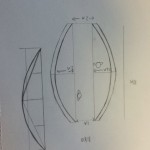
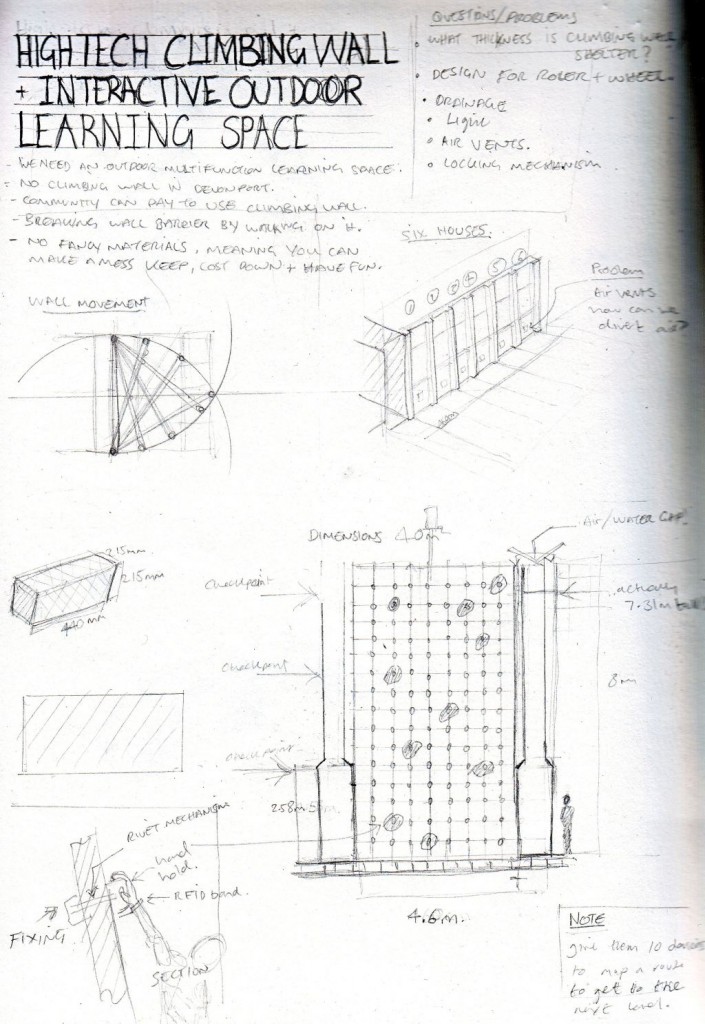
The brief sought to create a community archive or museum with the design incorporating some interactive element. The architects worked on the design for the building as we developed the prototype. We came up with a wavy LED wall concept that would be built into one of the walls of the building. The wall would be used for democratic visualisations, with a question about the redevelopment of the town displayed on a screen and a touch screen voting interface. The display could also be used to visualise other elections and votes of interest around the world as well as other information all year round.

DAT302 – RFID

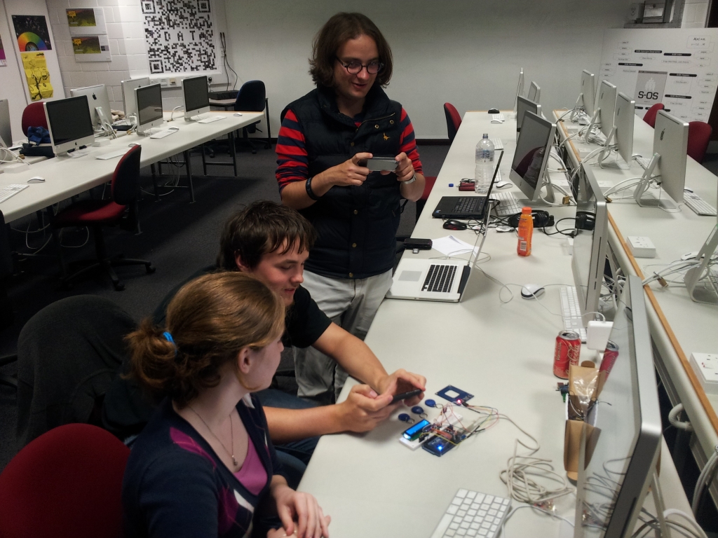
The RFID reader uses a serial connection with the Arduino to pass data to it. The easiest way to do this is to use the pins that are also used for the USB serial connection; the disadvantage of this is that the USB connection cannot be used and that there is only one. The SoftwareSerial library allows us to create serial connections with other pins.

We had a problem with our code for the RFID reader where it would freeze the Arduino unless it was able to read an RFID tag. It turned out that we were using an old version of Arduino and since Arduino 1.0 SoftwareSerial has been based on NewSoftwareSerial which fixed the freezing problem. Another problem we had was that we were using pins on the Arduino Mega 2560 that do not support a feature necessary for SoftwareSerial. Both of these problems would have been solved by actually reading the reference.

We made use of the LCD display used in Fickleduino to display the RFID tags owners’ names.